Friday 11 December 2015

Shuttle Valve?

                A shuttle valve allows two alternate flow sources to be connected in a one-branch circuit. The valve has two inlets P1 and P2 and one outlet A. Outlet A receives flow from an inlet that is at a higher pressure. Figure 1.5 shows the operation of a shuttle valve. If the pressure at P1 is greater than that at P2, the ball slides to the right and allows P1 to send flow to outlet A. If the pressure at P2 is greater than that at P1, the ball slides to the left and P2 supplies flow to outlet A .
               One application for a shuttle valve is to have a primary pump inlet P1 and a secondary pump inlet P2 connected to the system outlet A The secondary pump acts as a backup, supplying flow to the system if the primary pump loses pressure. A shuttle valve is called an “OR” valve because receiving a pressure input signal from either P1 or P2 causes a pressure output signal to be sent to A

Pilot-Operated check Valve?


               A pilot-operated valve along with its symbol is shown in Fig. This type of check valve always permits free flow in one direction but permits flow in the normally blocked opposite direction only if the pilot pressure is applied at the pilot pressure point of the valve. The check valve poppet has the pilot piston attached to the threaded poppet stem by a nut. The light spring holds the poppet seated in a no-flow condition by pushing against the pilot piston. The purpose of the separate drain port is to prevent oil from creating a pressure build-up at the bottom of the piston. The dashed line in the graphical symbol represents the pilot pressure line connected to the pilot pressure port of the valve. Pilot check valves are used for locking hydraulic cylinders in position

Advantages and Disadvantages of a Poppet Valve?


Advantages of a poppet valve 

 Virtually zero leakage in closed position.

 Poppet elements do not stick even when left under pressure for long periods
.
 Fast, consistent response time: typically 15 ms.

Disadvantages of a Poppet Valve A poppet valve has the following disadvantages:

 Axial pressure balance is impossible and considerable force may be needed to open the poppet against the flow at a high pressure. This limits valves that have direct mechanical actuation to low flow duties.

 Generally individual poppets are required for each flow path that significantly increases the complexity of multi-port valves
.
 Lapping and super finishing of valves add cost.

Check Valve?


               The simplest DCV is a check valve. A check valve allows flow in one direction, but blocks the flow in the opposite direction. It is a two-way valve because it contains two ports
               provides two schematic drawings showing the operation of a poppet check valve. A poppet is a specially shaped plug element held on a valve seat by a light spring. Fluid flows through the valve in the space between the seat and poppet. In the free flow direction, the fluid pressure overcomes the spring force. If the flow is attempted in the opposite direction, the fluid pressure pushes the poppet in the closed position. Therefore, no flow is permitted.

Graphical symbols of Actuating Devices?


What is meant by Actuating Devices?

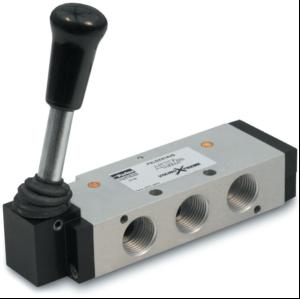
                      Direction control valves may be actuated by a variety of methods. Actuation is the method of moving the valve element from one position to another. There are four basic methods of actuation: Manual, mechanical, solenoid-operated and pilot-operated. Several combinations of actuation are possible using these four basic methods. 

Manually operated: In manually operated DCVs, the spool is shifted manually by moving a handle pushing a button or stepping on a foot pedal. When the handle is not operated, the spool returns to its original position by means of a spring.

Mechanically operated: The spool is shifted by mechanical linkages such as cam and rollers.

Solenoid operated: When an electric coil or a solenoid is energized, it creates a magnetic force that pulls the armature into the coil. This causes the armature to push the spool of the valve.

Pilot operated: A DCV can also be shifted by applying a pilot signal (either hydraulic or pneumatic) against a piston at either end of the valve spool. When pilot pressure is introduced, it pushes the piston to shift the spool.

4/3 Valves ?

4/2 and 5/2 Valve ?

2/2 and 3/2 Valves ?

Thursday 10 December 2015

Classification of DCVs based on the Construction of Internal Moving Parts?


                    In this type, the spool is rotated to change the direction of fluid. It has longitudinal grooves. The rotary spools are usually manually operated. 

                       This consists of a specially shaped spool and a means of positioning the spool. The spool is fitted with precision into the body bore through the longitudinal axis of the valve body. The lands of the spool divide this bore into a series of separate chambers. The ports of the valve body lead into these chambers and the position of the spool determines the nature of inter-connection between the ports.

Classification of DCVs based on the Control Method?


                              A valve is actuated directly on the valve spool. This is suitable for small sized valves.
 
                              A valve is actuated by a pilot line or using a solenoid or by the combination of electro hydraulic and electro-pneumatic means. The use of solenoid reduces the size of the valve. This is suitable for large-sized valves. 

Classification of DCVs based on Design Characteristics?


Based on design characteristics, DCVs can be classified as follows:

+) An internal valve mechanism that directs the flow of fluid. Such a mechanism can either be a poppet, a ball, a sliding spool, a rotary plug or a rotary disk.

+) Number of switching positions (usually 2 or 3).

+) Number of connecting ports or ways.

+) Method of valve actuation that causes the valve mechanism to move into an alternate position.

Classification of DCVs based Fluid Path?

Purpose of DCV's?


 To start, stop, accelerate, decelerate and change the direction of motion of a hydraulic actuator. 

 To permit the free flow from the pump to the reservoir at low pressure when the pump’s delivery is not needed into the system. 

 To vent the relief valve by either electrical or mechanical control. 

 To isolate certain branch of a circuit.

types of valves?


1. Directional control valves (DCVs): 
                      They determine the path through which a fluid transverses a given circuit. 

Pressure control valves: 
                     They protect the system against overpressure, which may occur due to a sudden surge as valves open or close or due to an increase in fluid demand. 

2. Flow control valves: 
               Shock absorbers are hydraulic devices designed to smooth out pressure surges and to dampen hydraulic shock. In addition, the fluid flow rate must be controlled in various lines of a hydraulic circuit. For example, the control of actuator speeds can be accomplished through use of flow control valves. Non-compensated flow control valves are used where precise speed control is not required because the flow rate varies with pressure drop across a flow control valve. It is important to know the primary function and operation of various types of control components not only for good functioning of a system, but also for discovering innovative methods to improve the fluid power system for a given application.

Tuesday 8 December 2015

WHAT IS THE FUNCTION OF PRESSURE RELIEF VALVE?

A pressure Relief Valve is a safety device designed to protect a pressurized vessel or system during an over pressure event.
An over pressure event refers to any condition which would cause pressure in a vessel or system to increase beyond the specified design pressure or maximum allowable working pressure (MAWP).
The primary purpose of a pressure Relief Valve is protection of life and property by venting fluid from an over pressurized vessel.
Many electronic, pneumatic and hydraulic systems exist today to control fluid system variables, such as pressure, temperature and flow. Each of these systems requires a power source of some type, such as electricity or compressed air in order to operate. A pressure Relief Valve must be capable of operating at all times, especially during a period of power failure when system controls are non functional. The sole source of power for the pressure Relief Valve, therefore, is the process fluid.


Once a condition occurs that causes the pressure in a system or vessel to increase to a dangerous level, the pressure Relief Valve may be the only device remaining to prevent a catastrophic failure. Since reliability is directly related to the complexity of the device, it is important that the design of the pressure Relief Valve be as simple as possible.

The pressure Relief Valve must open at a predetermined set pressure, flow a rated capacity at a specified over pressure, and close when the system pressure has returned to a safe level. Pressure Relief Valves must be designed with materials compatible with many process fluids from simple air and water to the most corrosive media. They must also be designed to operate in a consistently smooth and stable manner on a variety of fluids and fluid phases.

Wednesday 25 November 2015

WHAT IS AN ACCUMULATOR?

A hydraulic accumulator is a device in which potential energy is stored in the form of a compressed gas or spring, or by a raised weight to be used to exert a force against a relatively in compressible fluid.
They are used in fluid power systems to accumulate energy and to smooth out pulsations. A hydraulic system utilizing an accumulator can use a smaller fluid pump since the accumulator stores energy from the pump during low demand periods. This energy is available for instantaneous use, released upon demand at a rate many times greater than could be supplied by the pump alone.
A hydraulic accumulator is a pressure storage reservoir in which a non-compressible hydraulic fluid is held under pressure by an external source. The external source can be a spring, a raised weight, or a compressed gas. An accumulator enables a hydraulic system to cope with extremes of demand using a less powerful pump, to respond more quickly to a temporary demand, and to smooth out pulsations. It is a type of energy storage device.
Accumulators can also act as surge or pulsation absorbers, much as an air dome is used on pulsating piston or rotary pumps. They will cushion hydraulic hammer, reducing shocks caused by rapid operation or sudden starting and stopping of power cylinders in a hydraulic circuit.
There are four principal types of accumulators, the weight loaded piston type, diaphragm (or bladder) type, spring type and the hydro pneumatic piston type. The weight loaded type was the first used but is much larger and heavier for its capacity than modern piston and bladder types. Both the weighted type, and mechanical spring type are very seldom used today. The hydro-pneumatic types use a gas as a spring cushion in conjunction with a hydraulic fluid, the gas and fluid being separated by a thin diaphragm or a piston. Tobul  accumulators, having an aluminum piston of low inertia as standard equipment, are superior to other makes in absorbing either high or low frequency pulsations.


Tuesday 24 November 2015

WHAT IS COMPRESSOR?

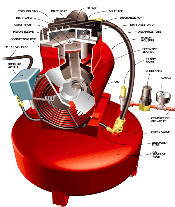
An air compressor is a device that converts power into potential energy stored in pressurized air .By one of several methods, an air compressor forces more and more air into a storage tank, increasing the pressure. When tank pressure reaches its upper limit the air compressor shuts off. The compressed air, then, is held in the tank until called into use. The energy contained in the compressed air can be used for a variety of applications, utilizing the kinetic energy of the air as it is released and the tank depressurizes. When tank pressure reaches its lower limit, the air compressor turns on again and re-pressurizes the tank.


WHAT IS THE FUNCTION OF DIRECTIONAL CONTROL VALVE?

To change the direction of airflow to and from the cylinder, we use a directional control valve. The moving part in a directional control valve will connect and disconnect internal flow passages within the valve body. This action results in a control of airflow direction.. The typical directional control valve consists of a valve body with four internal flow passages within the valve body and a sliding spool. Shifting the spool alternately connects a cylinder port to supply pressure or the exhaust port. With the spool in the position where the supply pressure is connected to port A and port B is connected to the exhaust port, the cylinder will extend. Then, with the spool in the other extreme position, supply pressure is connected to port B and port A is connected to the exhaust port, now the cylinder retracts. With a directional control valve in a circuit, the cylinder's piston rod can be extended or retracted and work performed


WHAT ARE THE TYPE OF PNEUMATIC CYLINDER USED IN INDUSTRIES?

The three pneumatic cylinders we discuss below are:
  • Single-acting cylinders
  • Double-acting cylinders
  • Telescoping cylinders

Single-acting cylinders (SAC) use pressure that forms from compacted air. In majority of cases, the extension SAC cylinders have is very limited due to the amount of space the compacted spring takes.
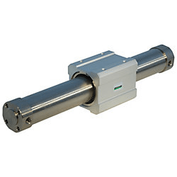
Double-acting cylinders (DAC) use air pressure in order to retract strokes and move in range. Two parts make up this cylinder, both of which let the air in. One is for outstroke and the other, in-stroke.

Telescoping cylinders, also known as telescopic cylinders come in single-acting and double-acting modes. Their designs allow for much longer strokes and tend to be reserved for uses where the piston has to face minimal side loading.

PNEUMATIC SYSTEM MEANS WHAT ?


Pneumatic systems 


            A pneumatic system is a system that uses compressed air to transmit and control energy. Pneumatic systems are used in controlling train doors, automatic production lines, mechanical clamps, etc.A pneumatic system controlled through manual or automatic solenoid valves is selected when it provides a lower cost, more flexible, or safer alternative to electric motors and actuators.             

                                         CLICK HERE FOR MORE DETAILS  

Sunday 22 November 2015

WHAT ARE THE SPECIFICATION IS TO BE CONSIDER WHILE SELECTING A CYLINDER?

The specifications that need to be considered while purchasing a hydraulic cylinder are:


•  Bore DiameterIt is the diameter of the cylinder bore.

•  Maximum operating pressure: The maximum working pressure a cylinder can carry is known as maximum operating pressure.

•  Rod Diameter: It is the diameter of the piston or the rod that are used in hydraulic cylinders.

•  Stroke: The distance traveled by a piston in a hydraulic cylinder is known as stroke. The length of a stroke could be several feet, or a fraction of an inch.

•  Type Of Cylinder: The different types of cylinders are tie-rod cylinder, ram cylinder and welded cylinder.

Tie-rod cylinder: These types of hydraulic cylinders make use of a single or multiple tie-rods to provide extra stability to the cylinder.   The tie-rods are mostly installed on the exterior diameter of the cylinder. The tie-rods carry most of the load in this type of hydraulic cylinder.

Welded cylinder: There are heavy-duty welded cylinders used to balance the cylinder. The welded cylinders are smooth hydraulic cylinders.

Ram cylinders: As the name suggests, this cylinders act as a ram.   The cross-section of the moving components is half of the cross-section area of the piston rod.   These hydraulic ram cylinders are not used to push and are mostly used to pull. The ram cylinder is a hydraulic cylinder that is used in applications of high pressure.

                                            CLICK HERE FOR MORE DETAILS

WHAT ARE THE COMPONENTS USED IN HYDRAULIC SYSTEM?


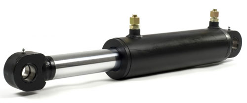
The various parts are the cylinder bottom, cylinder bottom connection cylinder barrel, and cylinder head. It also consists of the piston, piston rod, and the piston rod connection. And some of the hydraulic cylinders may comprise of the feet. These are used to mount the barrels.
The cylinder barrel is a thick tube that has to be machined from the inside. The interior of the barrel is honed or ground and in some cases both. The cylinder barrel and the bottom of the cylinder are welded together in most of the hydraulic cylinders.
This welding of the bottom of the cylinder to the barrel can damage the interior of the barrel. Hence, it is preferred to have the two screwed together. This type of connection will be helpful during repairs or maintenance of the cylinder barrel. On the other hand, the barrel is connected to the cylinder head with a lock.
There is a simple lock system used for a simple cylinder. In most of the hydraulic cylinders the flanged or screwed connections are used. The best type of connections and most expensive connections are the flanged connections. It is considered to be the best type of connection because before machining a flange is welded onto the tube.
The other positive aspects are that the flange is always bolted and can be removed easily when required. The disconnection process as well as the alignment process while mounting is much tougher for the bigger hydraulic cylinders. This problem in particular arises where the screw size is between 300 mm to 600 mm.
There should be no bending moments implied on the hydraulic cylinder as they are applied in expansion and retraction actions. The single clevis connection with a ball bearing is considered to be the most appropriate connection, as all the above-mentioned problems do not arise.
                                     FOR MORE DETAIL CLICK HERE

HOW THE CYLINDER IS CLASSIFIED BASED ON ITS SPECIFICATION?


These cylinders are also known as Ram cylinders. These types of hydraulic cylinders are placed in an upright position. This is done so that once the supply of the fluid is stopped, the weight on the cylinder will make it return to its original position. The cylinders used in automobile service centers are a good example of the plunger cylinders.


Telescopic cylinders are also known as multistage hydraulic cylinders. These cylinders have at the most six stages. These are specially used in applications where there is less area. Telescopic cylinders can either be single action or double action. The stroke of these cylinders is long and is used in applications such as cranes and forklifts, etc.


The cable cylinders can either be hydraulic or pneumatic powered cylinders that are of the double acting type. These cylinders have long strokes and produce moderate force. The cable cylinders can be operated in limited space.


Diaphragm cylinders are of two types i.e. flat diaphragm and rolling diaphragm. These cylinders have zero leak around the piston.


                                                   CLICK HERE FOR MORE DETAILS

HOW THE HYDRAULIC CYLINDER CLASSIFIED BASED ON ITS FUNCTION?

In single acting cylinders the fluid is pressurized from only one side of the cylinder during both the expansion as well as the retraction process. A spring or an external load is used to return the cylinder top to its original position i.e. when pressure of the fluid is cut off.

In the double acting cylinders, the pressure from the fluid is applied in both the directions. Single cylinders that consist of springs are not used in large stroke applications because there are inherent mechanical problems associated with the spring. The double acting rods could be of two types

•  Single rod ended


WHAT IS THE BASIC FUNCTION OF PNEUMATIC CYLINDERS ?

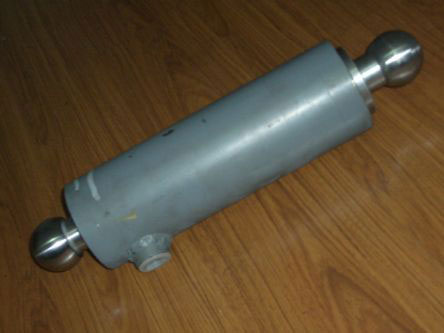
The hydraulic pressure in these cylinders is in the form of hydraulic fuels that are stored under pressure in these cylinders. The energy stored in these oils is converted into motion. In a complete hydraulic system, a hydraulic motor consists of one or more hydraulic cylinders. A pump regulates the oil-flow in the hydraulic system. The pump is a part of the generator of a hydraulic system. The hydraulic cylinders initiate the pressure of the oil, which cannot be more than that required by the load. A hydraulic cylinder consists of a cylindrical barrel, piston, and a piston rod. The piston that is placed within the barrel is connected to the piston rod. The cylinder bottom, and the cylinder head, closes the bottom and the head of the barrel respectively. The cylinder head is the side from where the piston rod exits the cylinder. The cylinder bottom and the piston rod are mounted with mounting brackets or clevises. The piston in the hydraulic cylinder consists of sliding rings and seals. The piston rod chamber and the bottom chamber are the two chambers within the cylinder. 


The piston rod starts moving outwards, as the hydraulic fluid is pumped into the bottom side of the hydraulic cylinder. In the reverse process, the hydraulic fluid is pushed back into the reservoir by the piston. The pressure in the cylinder is the ratio of unit force per unit piston area. The pressure generated in the piston rod chamber is the ratio of the unit load per the difference in the unit piston area and unit piston rod area. This calculation is used when the hydraulic fluid is let into the piston rod chamber as well as the fluid flows smoothly (without pressure) from the piston area to the reservoir. In this way, the expansion and retraction (push and pull) action of the hydraulic cylinder is generated.

    we also design some hydraulic cylinders for projects . 
                   for more detail    CLICK HERE


WHAT ARE ADVANTAGES AND DISADVANTAGES OF HYDRAULIC SYSTEM?

Advantages


  • The hydraulic system uses in compressible fluid which results in higher efficiency.  
  • It delivers consistent power output which is difficult in pneumatic or mechanical drive systems. 
  •  Hydraulic systems employ high density in compressible fluid. Possibility of leakage is less in hydraulic system as compared to that in pneumatic system. The maintenance cost is less. 
  • These systems perform well in hot environment conditions. 


 Disadvantages 

  •  The material of storage tank, piping, cylinder and piston can be corroded with the hydraulic fluid. Therefore one must be careful while selecting materials and hydraulic fluid. 
  •  The structural weight and size of the system is more which makes it unsuitable for the smaller instruments.
  •   The small impurities in the hydraulic fluid can permanently damage the complete system, therefore one should be careful and suitable filter must be installed.
  •   The leakage of hydraulic fluid is also a critical issue and suitable prevention method and seals must be adopted.
  •   The hydraulic fluids, if not disposed properly, can be harmful to the environment.

WHAT ARE THE APPLICATION OF HYDRAULIC SYSTEM?

  The hydraulic systems are mainly used for precise control of larger forces. The main applications of hydraulic system can be classified in five categories:

Industrial: Plastic processing machines, steel making and primary metal extraction applications, automated production lines, machine tool industries, paper industries, loaders, crushes, textile machinates, R & D equipment and robotic systems etc.

Mobile hydraulics: Tractors, irrigation system, earth moving equipment, material handling equipment, commercial vehicles, tunnel boring equipment, rail equipment, building and construction machinery and drilling rigs etc.

Automobiles: It is used in the systems like breaks, shock absorbs, steering system, wind shield, lift and cleaning etc.

Marine applications: It mostly covers ocean going vessels, fishing boats and navel equipment.


Aerospace equipment: There are equipment and systems used for rudder control, landing gear, breaks, flight control and transmission etc. which are used in airplanes, rockets and spaceships.

what is pump ?

pump is a mechanical device which is used to convert electrical 

energy into mechanical energy.a mechanical device using suction 

or pressure to raise or move liquids, compress gases, or force air

 into inflatable objects such as tyres.


Pumps operate by some mechanism and consume energy to

 perform mechanical work by moving the fluid. Pumps operate via 

many energy sources, including manual operation,

 electricity, engines, or wind power, come in many sizes, from 

microscopic for use in medical applications to large industrial 

pumps.
                                for more details    CLICK HERE


WHAT ARE THE DIFFERENT TYPES OF PUMPS USED IN HYDRAULIC SYSTEM?

Hydraulic pumps are manufactured depending on different functional and hydraulic system requirements, such as operating medium, required range of pressure, type of drive, etc. A large range of design principles and configurations exists behind hydraulic pumps. Consequently, not every pump can fully meet all sets of requirements to an optimum degree. Three different types of hydraulic pumps exist:
  • External gear pump
  • Internal gear pump
  • Gear ring pump
  • Screw spindle pump
  • Single chamber vane pump
  • Double chamber vane pump
  • Axial piston pump
  • Radial piston pump

WHAT IS hydraulic system ?

Hydraulic systems can be found today in a wide variety of applications, from small assembly processes to integrated steel and paper mill applications. Hydraulics enable the operator to accomplish significant work (lifting heavy loads, turning a shaft, drilling precision holes, etc.) with a minimum investment in mechanical linkage through the application of Pascal’s law, which states:
“Pressure applied to a confined fluid at any point is transmitted undiminished throughout the fluid in all directions and acts upon every part of the confining vessel at right angles to its interior surfaces and equally upon equal areas.


By applying Pascal’s law and Brahma’s application of it, it is evident that an input force of 100 pounds on 10 square inches will develop a pressure of 10 pounds per square inch throughout the confined vessel. This pressure will support a 1000-pound weight if the area of the weight is 100 square inches.
The principle of Pascal’s law is realized in a hydraulic system by the hydraulic fluid that is used to transmit the energy from one point to another. Because hydraulic fluid is nearly in compressible, it is able to transmit power instantaneously.


      we are also using this principle for making our projects. for more details

Saturday 21 November 2015

what are major components used in hydraulic system?

The major components that make up a hydraulic system are the reservoir, pump, valve(s) and actuator(s) (motor, cylinder, etc.).
Reservoir

The purpose of the hydraulic reservoir is to hold a volume of fluid, transfer heat from the system, allow solid contaminants to settle and facilitate the release of air and moisture from the fluid.
Pump

The hydraulic pump transmits mechanical energy into hydraulic energy. This is done by the movement of fluid which is the transmission medium. There are several types of hydraulic pumps including gear, vane and piston. All of these pumps have different sub types intended for specific applications such as a bent-axis piston pump or a variable displacement vane pump. All hydraulic pumps work on the same principle, which is to displace fluid volume against a resistant load or pressure.
Valves

Hydraulic valves are used in a system to start, stop and direct fluid flow. Hydraulic valves are made up of poppets or spools and can be actuated by means of pneumatic, hydraulic, electrical, manual or mechanical means.
Actuators

Hydraulic actuators are the end result of Pascal’s law. This is where the hydraulic energy is converted back to mechanical energy. This can be done through use of a hydraulic cylinder which converts hydraulic energy into linear motion and work, or a hydraulic motor which converts hydraulic energy into rotary motion and work. As with hydraulic pumps, hydraulic cylinders and hydraulic motors have several different sub types. each intended for specific design applications.

            we are used some of these components in our projects.for more details