Thursday, 10 December 2015

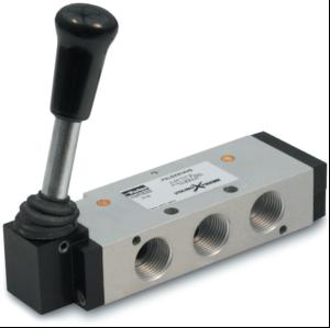
Classification of DCVs based on Design Characteristics?


Based on design characteristics, DCVs can be classified as follows:

+) An internal valve mechanism that directs the flow of fluid. Such a mechanism can either be a poppet, a ball, a sliding spool, a rotary plug or a rotary disk.

+) Number of switching positions (usually 2 or 3).

+) Number of connecting ports or ways.

+) Method of valve actuation that causes the valve mechanism to move into an alternate position.

Classification of DCVs based Fluid Path?

Purpose of DCV's?


 To start, stop, accelerate, decelerate and change the direction of motion of a hydraulic actuator. 

 To permit the free flow from the pump to the reservoir at low pressure when the pump’s delivery is not needed into the system. 

 To vent the relief valve by either electrical or mechanical control. 

 To isolate certain branch of a circuit.

types of valves?


1. Directional control valves (DCVs): 
                      They determine the path through which a fluid transverses a given circuit. 

Pressure control valves: 
                     They protect the system against overpressure, which may occur due to a sudden surge as valves open or close or due to an increase in fluid demand. 

2. Flow control valves: 
               Shock absorbers are hydraulic devices designed to smooth out pressure surges and to dampen hydraulic shock. In addition, the fluid flow rate must be controlled in various lines of a hydraulic circuit. For example, the control of actuator speeds can be accomplished through use of flow control valves. Non-compensated flow control valves are used where precise speed control is not required because the flow rate varies with pressure drop across a flow control valve. It is important to know the primary function and operation of various types of control components not only for good functioning of a system, but also for discovering innovative methods to improve the fluid power system for a given application.

Tuesday, 8 December 2015

WHAT IS THE FUNCTION OF PRESSURE RELIEF VALVE?

A pressure Relief Valve is a safety device designed to protect a pressurized vessel or system during an over pressure event.
An over pressure event refers to any condition which would cause pressure in a vessel or system to increase beyond the specified design pressure or maximum allowable working pressure (MAWP).
The primary purpose of a pressure Relief Valve is protection of life and property by venting fluid from an over pressurized vessel.
Many electronic, pneumatic and hydraulic systems exist today to control fluid system variables, such as pressure, temperature and flow. Each of these systems requires a power source of some type, such as electricity or compressed air in order to operate. A pressure Relief Valve must be capable of operating at all times, especially during a period of power failure when system controls are non functional. The sole source of power for the pressure Relief Valve, therefore, is the process fluid.


Once a condition occurs that causes the pressure in a system or vessel to increase to a dangerous level, the pressure Relief Valve may be the only device remaining to prevent a catastrophic failure. Since reliability is directly related to the complexity of the device, it is important that the design of the pressure Relief Valve be as simple as possible.

The pressure Relief Valve must open at a predetermined set pressure, flow a rated capacity at a specified over pressure, and close when the system pressure has returned to a safe level. Pressure Relief Valves must be designed with materials compatible with many process fluids from simple air and water to the most corrosive media. They must also be designed to operate in a consistently smooth and stable manner on a variety of fluids and fluid phases.

Wednesday, 25 November 2015

WHAT IS AN ACCUMULATOR?

A hydraulic accumulator is a device in which potential energy is stored in the form of a compressed gas or spring, or by a raised weight to be used to exert a force against a relatively in compressible fluid.
They are used in fluid power systems to accumulate energy and to smooth out pulsations. A hydraulic system utilizing an accumulator can use a smaller fluid pump since the accumulator stores energy from the pump during low demand periods. This energy is available for instantaneous use, released upon demand at a rate many times greater than could be supplied by the pump alone.
A hydraulic accumulator is a pressure storage reservoir in which a non-compressible hydraulic fluid is held under pressure by an external source. The external source can be a spring, a raised weight, or a compressed gas. An accumulator enables a hydraulic system to cope with extremes of demand using a less powerful pump, to respond more quickly to a temporary demand, and to smooth out pulsations. It is a type of energy storage device.
Accumulators can also act as surge or pulsation absorbers, much as an air dome is used on pulsating piston or rotary pumps. They will cushion hydraulic hammer, reducing shocks caused by rapid operation or sudden starting and stopping of power cylinders in a hydraulic circuit.
There are four principal types of accumulators, the weight loaded piston type, diaphragm (or bladder) type, spring type and the hydro pneumatic piston type. The weight loaded type was the first used but is much larger and heavier for its capacity than modern piston and bladder types. Both the weighted type, and mechanical spring type are very seldom used today. The hydro-pneumatic types use a gas as a spring cushion in conjunction with a hydraulic fluid, the gas and fluid being separated by a thin diaphragm or a piston. Tobul  accumulators, having an aluminum piston of low inertia as standard equipment, are superior to other makes in absorbing either high or low frequency pulsations.


Tuesday, 24 November 2015

WHAT IS COMPRESSOR?

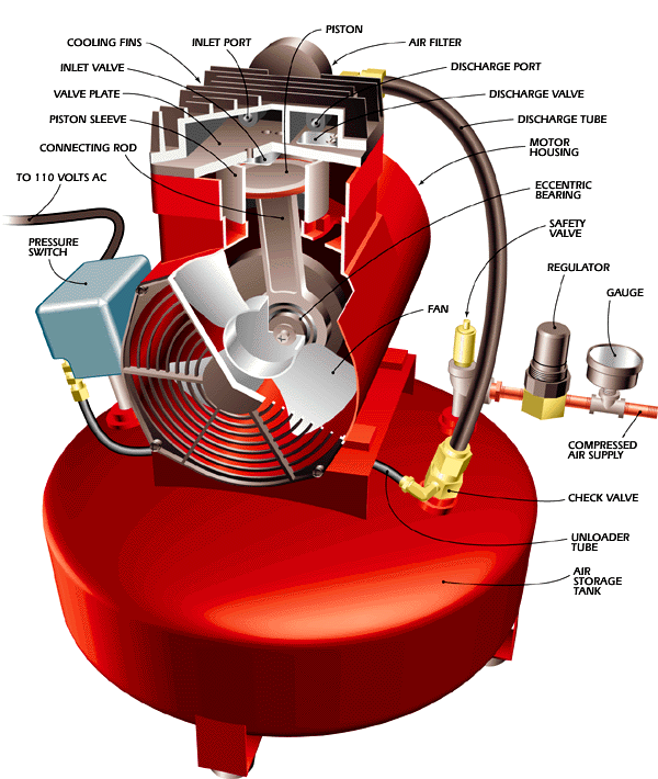
An air compressor is a device that converts power into potential energy stored in pressurized air .By one of several methods, an air compressor forces more and more air into a storage tank, increasing the pressure. When tank pressure reaches its upper limit the air compressor shuts off. The compressed air, then, is held in the tank until called into use. The energy contained in the compressed air can be used for a variety of applications, utilizing the kinetic energy of the air as it is released and the tank depressurizes. When tank pressure reaches its lower limit, the air compressor turns on again and re-pressurizes the tank.